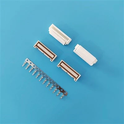
Technical Specifications
|
Parameter |
Specification |
|
Product Type |
1.25mm Dual-Row Wire-to-Board Connector |
|
Circuit Count |
14 circuits |
|
Pitch |
1.25mm |
|
Rated Current |
1A AC/DC |
|
Rated Voltage |
50V DC |
|
Operating Temperature |
-25°C to +105°C |
|
Contact Resistance |
≤70 mΩ Max. |
|
Insulation Resistance |
≥100 MΩ Min. |
|
Withstanding Voltage |
500V AC / 1 minute |
|
Housing Material |
PA66 UL94V-0, White |
|
Terminal Material |
Phosphor Copper, Gold Plated / Tin Plated |
|
SMT Pin Body |
LCP UL94V-0, Gray |
|
SMT Pin Material |
Phosphor Copper, Tin Plated |
|
Pin Holder Ground Disc |
Brass, Tin Plated |
14-Circuit Connector System
|
Component |
14-Circuit Model |
Configuration |
|
Crimp Housing |
A1259HF207AKP69079 |
Dual-row, Positive Lock |
|
Female Crimp Terminal |
A1259M0AGF002 |
Gold plated |
|
Female Crimp Terminal |
A1259M0ATP002 |
Tin plated |
|
Vertical SMT Header |
A1259VS207AALPGFB8001 |
Gold plated |
|
Vertical SMT Header |
A1259VS207AALPTPB8001 |
Tin plated |
|
Right-Angle SMT Header |
A1259RS207AALPGFB8001 |
Gold plated |
|
Right-Angle SMT Header |
A1259RS207AALPTPB8001 |
Tin plated |
Connection Architecture:
Wire → Female Crimp Terminal → 14-Circuit Housing → SMT Header → PCB
GHDR-14V-S-1 Cross-Reference
|
Reference Family |
Reference Model |
Corresponding A1259 Model |
|
JST Housing |
GHDR-14V-S-1(F) |
A1259HF207AKP69079 |
|
JST Gold Crimp Terminal |
SGHD-002GA-P0.2 |
A1259M0AGF002 |
|
JST Tin Crimp Terminal |
SGHD-002T-C0.2A |
A1259M0ATP002 |
|
JST Vertical SMT, Gold |
BM14B-GHDS-G-TF(LF)(SN) |
A1259VS207AALPGFB8001 |
|
JST Vertical SMT, Tin |
BM14B-GHDS-TF(LF)(SN) |
A1259VS207AALPTPB8001 |
|
JST Right-Angle SMT, Gold |
SM14B-GHDS-G-TF(LF)(SN) |
A1259RS207AALPGFB8001 |
|
JST Right-Angle SMT, Tin |
SM14B-GHDS-TF(LF)(SN) |
A1259RS207AALPTPB8001 |
|
JAM Vertical SMT, Tin |
STW12-14WV-ET |
A1259VS207AALPTPB8001 |
|
JAM Right-Angle SMT, Tin |
STW12-14WH-ET |
A1259RS207AALPTPB8001 |
Alternative-Source Evaluation & Project Integration
Mating interface: Confirm the existing cable-side and PCB-side connector geometry, insertion direction and locking structure.
14-circuit configuration: Verify the dual-row pin arrangement and terminal position against the existing assembly.
PCB integration: Check pad layout, pin position, mounting orientation and available board space before changing to a vertical or right-angle header.
Terminal configuration: Specify gold- or tin-plated crimp terminals according to the contact requirements of the application.
Cable termination: Confirm applicable wire gauge, crimp requirements and cable construction before production.
Mechanical clearance: Check housing dimensions, mating clearance and surrounding components in the final assembly.
Engineering samples: Samples can be used for mating tests, PCB assembly checks and dimensional verification before volume purchasing.
Packaging & Logistics
Packaging: Connector components are packed in protective PE bags and export cartons; SMT headers are available in reel packaging.
MOQ: 1,000 pcs per model for standard orders; samples can be arranged before production.
Lead Time: 7–15 working days for standard orders; larger quantities or special requirements may require additional time.
Shipping & Terms: Express, air and sea freight are available, with FOB, CIF and DDP terms supported.
FAQ
Q: What applications is the GHDR-14V-S-1 suitable for?
A: The 14-circuit dual-row format is suitable for compact wire-to-board connections in control boards, consumer electronics, industrial electronics, instrumentation and other PCB-based assemblies where multiple signal or low-power circuits need to be connected within limited board space.
Q: Is the connector suitable for automated PCB assembly?
A: The SMT header versions are designed for PCB mounting and can be supplied in reel packaging for applicable configurations. Production teams can evaluate the header geometry and packaging against their existing SMT assembly process.
Q: What quality controls are performed during connector production?
A: Quality control can include incoming material inspection, dimensional inspection, terminal and housing checks, contact resistance testing, insulation resistance testing and withstand-voltage testing according to the confirmed specification.
Q: Can you provide quality inspection documents with an order?
A: Inspection records and product documentation can be provided according to the agreed order requirements. Buyers can specify required inspection items or documentation during the quotation and approval stage.
Q: How do you control dimensional consistency between production batches?
A: Critical housing, terminal and SMT header dimensions are checked against the approved product specification. Production samples and inspection records can be retained as references for subsequent orders to help maintain specification consistency.
Q: Can the connector be evaluated before approving it for production?
A: Yes. Engineering samples can be used for internal validation such as connector mating, cable termination, PCB assembly and functional testing before the connector is released for volume production.
Q: Can you support customer-specific inspection requirements?
A: Yes. Inspection requirements can be discussed before production, including dimensional checkpoints, electrical tests, appearance criteria and sampling requirements. This is useful when the connector is subject to an established incoming-quality standard.
Q: What should buyers check during incoming inspection?
A: Typical checks include part number and circuit configuration, housing and terminal condition, plating appearance, key dimensions, terminal position and electrical performance where required. The inspection criteria should follow the approved drawing or product specification.
Q: Can the connector be used in an existing equipment design without redesigning the entire assembly?
A: The possibility depends on the existing mating connector, PCB layout, mechanical envelope and electrical requirements. If these interfaces are validated against the proposed configuration, the connector can be evaluated as an alternative source without assuming a complete system redesign.
Q: What information helps determine whether this connector fits a new application?
A: For a new project, useful information includes the required circuit count, PCB mounting orientation, cable type, wire gauge, expected electrical load, operating temperature, mating requirements and available installation space. These details help determine the appropriate connector configuration and validation requirements.
Hot Tags: alternative ghdr-14v-s-1, China alternative ghdr-14v-s-1 suppliers, factory, 1 25mm pitch, A1255 FI S alternative FI S 1 25mm Housing Terminal Cbale Wafer, A1258 GH alternative GH 1 25mm Housing Terminal Cable SMT Wafer, A1259 GHD alternative GHD 1 25 Buckle Housing Terminal Wafer Cable, Alternative GHDR 10V S 1, Alternative GHDR 14V S 1